
OWASP FSTM, stage 2: Obtaining IOT device firmware
Table of Contents

During the analysis phase, getting hold of the firmware is essential. This article explains possible mechanisms for obtaining IoT device firmware and for collecting other data of interest from the embedded system backplane
In the previous step of the methodology, data about the device was collected without accessing the device (using open sources). The objective of step 2 of the OWASP FSTM (Firmware Security Testing Methodology) methodology is obtaining IOT device firmware if this was not achieved in the previous step (for example, by obtaining it from the manufacturer’s website).
There is no single valid method to achieve firmware extraction. Therefore, this article presents several alternatives, analyzing their pros and cons. The firmware extraction process can be simple or very costly depending on the device.
One of the key phases during this stage of the methodology is the identification of physical debug ports and memory chips as they are the most interesting ways to obtaining IOT device firmware. Throughout the article, some recommendations, and best practices for approaching this type of actions will be presented.
It’s important to understand the workflow behind firmware extraction at all levels. Sometimes there are limitations in the number of tools available, as there are not always adapters to read all hardware memories. Therefore, a good understanding of the basics behind each of the actions performed will make it possible to remedy the lack of certain tools and to manufacture some of them if necessary.
The focus of stage 2 of the OWASP FSTM methodology is on obtaining device firmware for further analysis. There is no single wildcard path for firmware extraction that applies to all devices. Therefore, this type of action sometimes requires creativity and lateral thinking on the part of the researcher.
Recommendations and good practices
- It’s always interesting to have more than one physical device of the model to be analyzed as there is a possibility of total/partial damage during firmware extraction (e.g., when desoldering the memory). It may also be necessary to use the same IoT device board as the electronic prototyping board (assuming its loss depending on the nature of the tests).
- In most cases the techniques presented in this article will be sufficient for firmware extraction, however, there may be devices on the market that require other techniques to obtain the firmware.
During a IoT security audit, obtaining the firmware is a priority to be able to perform most of the subsequent tasks.
Checking the operation of the device
First, before starting the extraction, it is necessary to check that the device is working properly. It seems trivial, but sometimes devices (even new ones) can have some problems when they are received. Shocks and exposure to heat or humidity can cause damage to electronic devices during transport and storage.
The researcher is responsible for deciding whether this step is appropriate for the type of analysis being performed. It is important to note that, in the case of a forensic investigation, connecting or disconnecting the device may lead to the removal or modification of evidence…
Download firmware from the manufacturer’s website
As discussed in the last article, the easiest way to obtain the firmware is from the manufacturer’s website. If the manufacturer has not made it available, other alternatives are presented below.
Download firmware directly
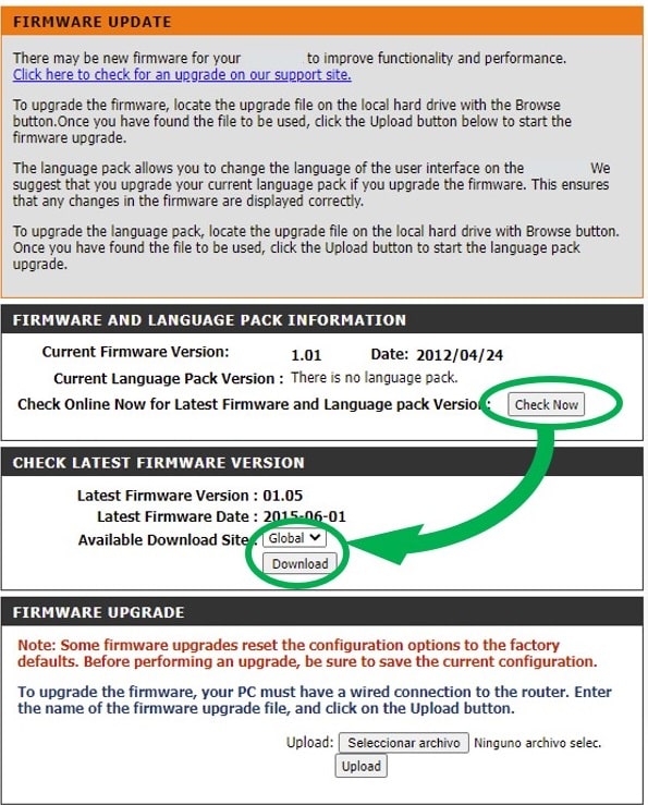
Whenever possible, you should check if the device is remotely upgradeable from internet. This is usually one of the easiest and quickest ways to get a copy of a device’s internal software. In some cases, it is possible to download the firmware directly via web.
As an example, in the case of this router the quickest solution is to access the configuration menu and check for pending updates.
Depending on the technology used, sometimes this trick only works if there are pending updates. In some cases, if the check requests are made via JavaScript, you can capture the URLs and the responses to the check requests to get the firmware even if your software version is the latest.
Intercept communications to obtain firmware
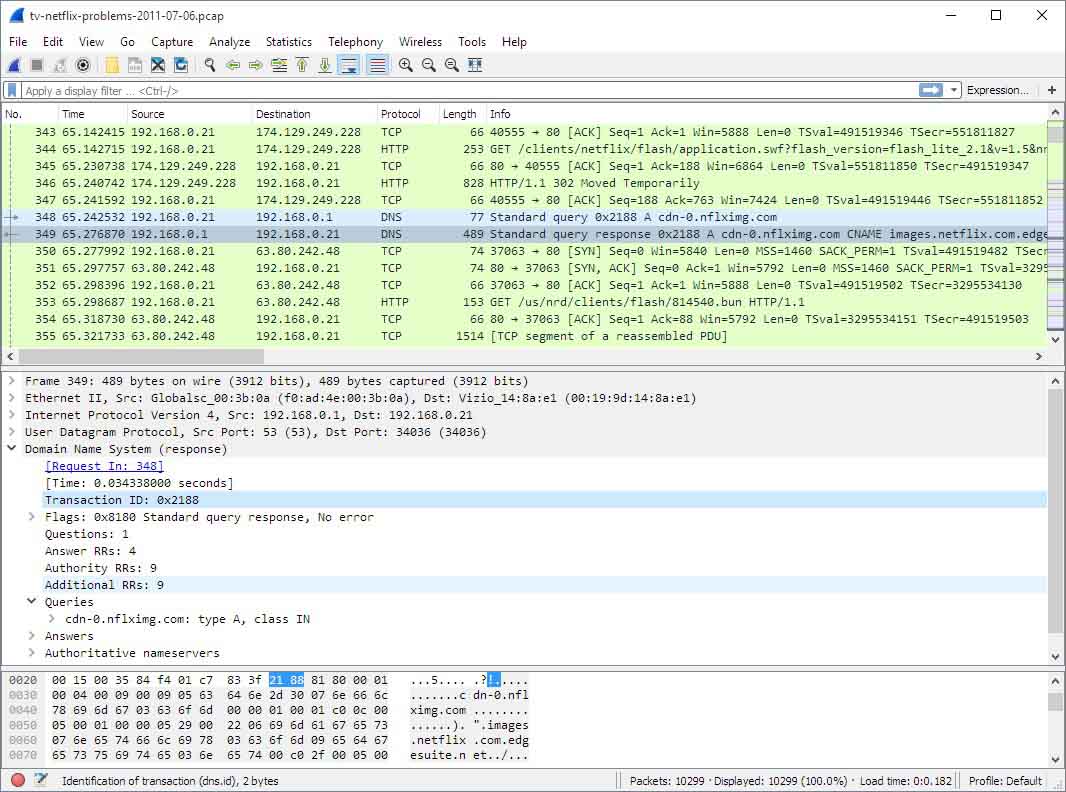
Another possible option, avoiding physical manipulation of the device, is to audit the communications. The objective is to capture IoT firmware/software updates in communications.
In these cases, the OWASP ISVS (IoT Security Verification Standard) guide is a great ally. One possible way to analyze device communications is Wireshark, as it provides several layers of filtering that allow to speed up much of the work.
Once the update process has been located, the communication objects could be dumped to a firmware file if this process has not been performed with the appropriate encryption.
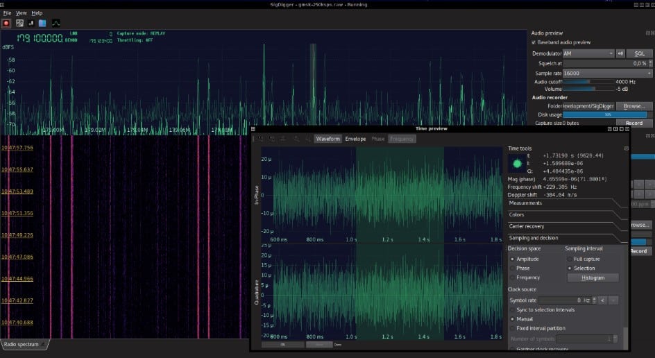
In some cases, devices use wireless communications for the update process. By using an SDR (or software defined radio), wireless communications can be intercepted and studied.
Depending on the case study, it may or may not be possible to demodulate these signals and extract the firmware during the upgrade process. Two possible programs that can facilitate this task are GNU-Radio and SigDigger.
IoT device hardware access
If the previous points have failed, there are still alternatives available to obtain the firmware, but it will be mandatory to analyze the hardware of the device. The objective will be to identify means to communicate with the device without restrictions when reading its firmware.
First, it is needed to disassemble the device. There is no one way at this job. Sometimes locate a screw hidden under a label, behind the rubber feet or even must disassemble the glass of a touch display… The goal is to have the board available in a way that allows us to identify all its parts.
Identification of communication port candidates
There are a multitude of ports of interest when reading the firmware of a device. Listed below in a table are some examples and general guidelines that serve as a summary of the most common ports on embedded devices.
The configurations shown in the table below are the most common. However, each manufacturer may choose to adopt solutions tailored to their needs. Therefore, the task of identifying these connections cannot always be classified in a simple table and requires a deeper knowledge of the tools that can be used and of the protocols themselves.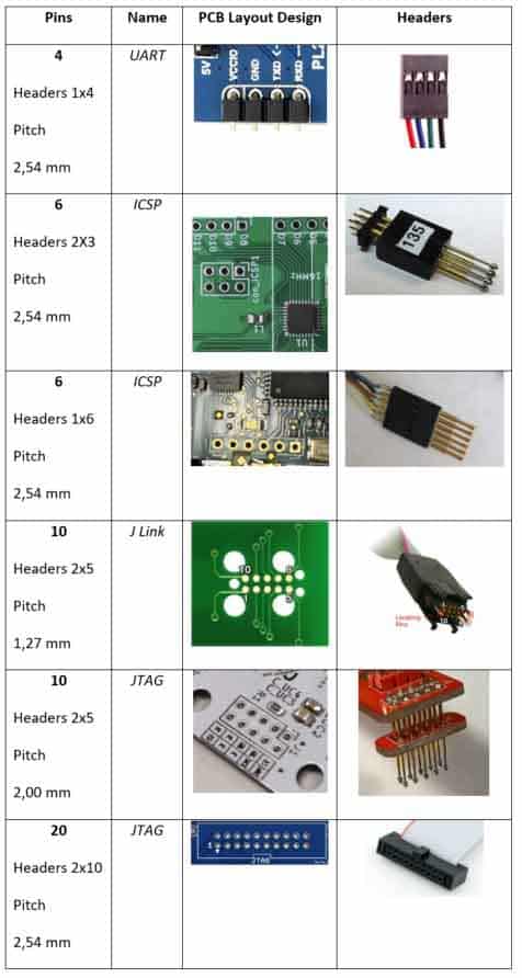
Some manufacturers choose not to expose the ports directly. In some cases, not labeling them is perceived as a security measure and in others, space constraints simply do not allow it. In these cases, it is likely to encounter test points that may contain some of these ports.
Tools for port verification
Some of the most common tools that can help identify port types are listed below with some of their uses.
Identifying the ports on a device will require knowledge of the protocols used on those ports. The following are some of the hints to simplify this process, not a detailed guide on how to do it.
Multimeter 
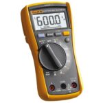
It can measure voltages, currents, continuity, resistive and capacitive values. In continuity measurement mode it allows us to easily identify ground points (0 V). Many devices have the metal parts exposed to ground for regulatory reasons and many connectors have the ground contacts marked and silk-screened. Knowing a ground point, we can identify which pins of a port are grounded with the continuity mode.
In voltage measurement mode it allows us to identify which power pins and at what voltage they operate. It could serve as an indicator if there is activity at any communication point (some idle ports are live, and others are fluctuating) but it is not a totally reliable use of this tool.
Oscilloscope
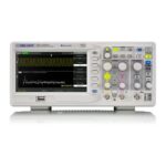
This is a much more complex and expensive tool than the multimeter. It allows us not only to measure the voltage on a port but also to visualize how this voltage changes over time. Thanks to this tool we can visualize the evolution of a signal to try to identify a specific protocol of those mentioned in the previous section.
The oscilloscope is a tool designed to analyze analog signals. If we already know the operating voltages of the protocol thanks to the use of the multimeter, since practically all signals treated by this type of devices are digital, it is recommended to use a logic analyzer for reasons of cost and ease of analysis.
Logic analyzer
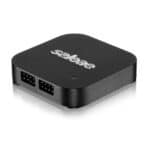
Like the oscilloscope, a logic analyzer allows us to see the evolution of a signal over time. The logic analyzer differs in that the latter does not allow a direct voltage measurement, it only allows digital measurements of a signal and will transmit whether the measured signal is at a logic low or high value (0 or 1).
This reduction of functionality with respect to the oscilloscope brings great benefits to our use case. It reduces costs and since we are working with digital signals, the analysis of the possible protocol found is greatly simplified. Many of these devices come with associated software that allows a semi-automatic recognition of the mentioned protocols.
USB-UART converter
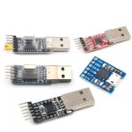
Once we have identified a candidate for this protocol, one way to verify the assumption is to connect to the port using a converter. It is very low cost and simplifies interacting with the port.
J-Link Debugger
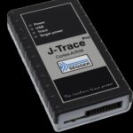 As with the UART, for other protocols we can use other adapters. Many of these debuggers support different protocols such as ICSP / JTAG / J-Link. There are a multitude of pin formats, but they are all based on the same 6 control signals and are the ports that are used to write or read the firmware and debug it.
Example of port identification
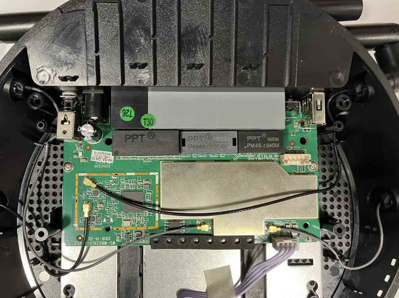
A visual inspection of the board has been performed on a test device. A port has been located that is even silkscreened and appears to indicate that it is a serial port.
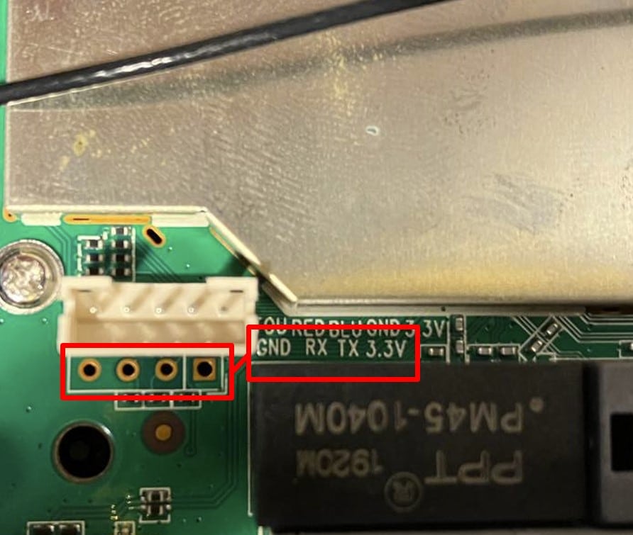
On this occasion, the same manufacturer has provided a legend to identify the pins, which is located next to the connector. We also proceed to check if the bus is powered and therefore in operation.
Between pin 2 and 4 of the port 3.3 V are measured (note that in the connectors pin 1 is always the one with the outer mark, in this case pin 1 is on the right side and coincides with the power positive legend). This coincides with the legend TX and GND respectively.
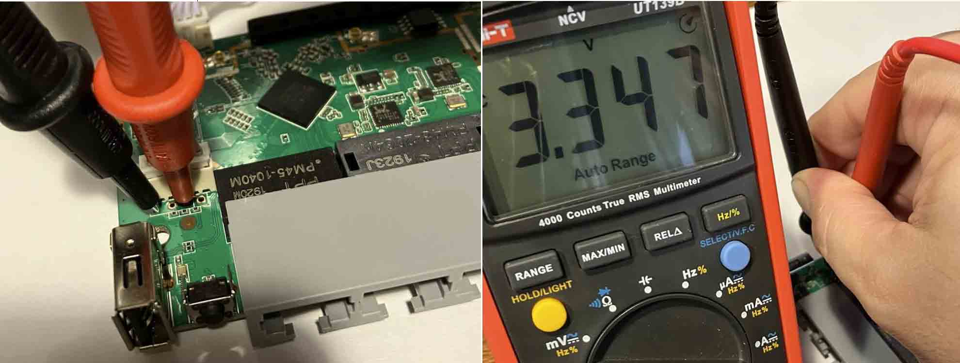
It is verified that between GND and TX (sending data) there are 3.347 V during start-up. Concluding that it is a UART-TTL and connecting to the corresponding adapter with the help of the clamps.
At this point an analysis and verification of the finding of a UART port could be done using the logic analyzer. This would give the assurance that it is one and an analysis could be made as to what speed it is operating at.
Given that the manufacturer has silkscreened the use of each pin and that it is known that the operating voltage is compatible with our USB-UART adapter, we proceed to its connection without the intermediate logic analysis to save time.
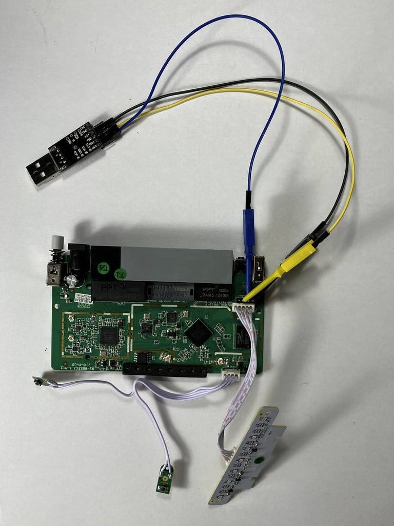
To remember two details on the UART-TTL buses:
- The TX / RX signals need a common reference between the studied circuit and the adapter. Therefore, it is necessary to connect the power supply negative (GND) in common to the two circuits.
- The TX / RX signals are cross connected, e.g., the TX of the writer circuit is connected to the RX of the reader device and vice versa.
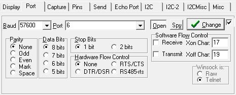
Once connected, the port speed is detected, this can be done with an autodetection process, generally the most used rates are 9,600, 57,600 and 115,200 bps. Docklight, Realterm or Coolterm are some of the most used programs to interact with UART adapters.
In Realterm the USB / UART-TTL interface was configured as shown in the screenshot.
After a few moments you can see that the system boot system is U-Boot.
![]()
In some cases, the boot loader allows the loading process to be interrupted and makes a shell available to the user. One of the common functionalities of boot loaders is to allow memory dump.
If the loading process is not interrupted, in this case study, the device exposes a shell with this welcome message:
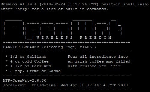
The researcher could evaluate different measures to make a firmware dump from this shell. In this case the firmware is busybox based and gives admin permissions. One option would be to do a “cat” of the block devices in the “/dev” folder and output the result in hexadecimal format with “printf” to later rebuild the image on our PC.
Read firmware directly from a circuit component
In other cases, no port will be accessible at all. It will be time to study the device board in depth to try to obtain the firmware. It is recommended to perform a recognition equivalent to the one shown.
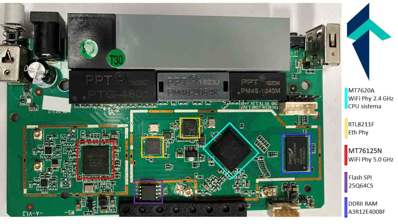
After the flash memory identification, it is confirmed that it is the 8-pin device with 1.27 mm pitch (SOIC8). This type of memory can be read with a standard EEPROM reader with the clamps for devices in this format.
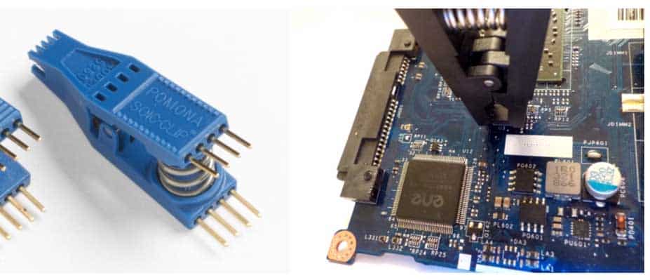
Its use is simple as shown in this article.
The reality regarding EEPROM memories is that there are an infinite number of formats, although the most common formats are listed in the following table.
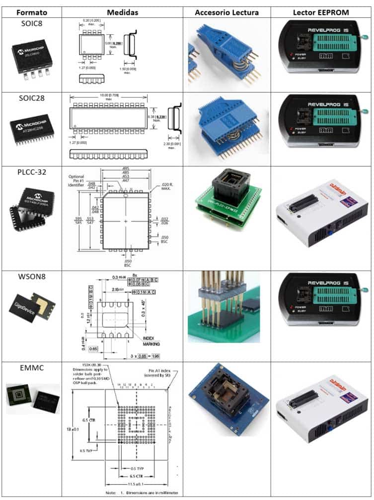
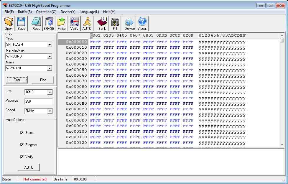
Many EEPROM reader/programmers are controlled by standard software. It usually has a device selection menu. In some models the manufacturer model is critical and in others not. It is therefore relevant to identify the manufacturer of the memory chip to be read.
In some cases, the memory models are not standard or not supported by the EEPROM reader manufacturer. In these cases one of the options is the design of a custom adapter.
There is no single way to do this work. Having specific tools and knowledge in electronics it will easier the process and the search for parallel methods.
IoT firmware security – Conclusions
Whenever possible, using the software option, even if the downloaded firmware is an update, may be sufficient to perform a security analysis.
When the way to obtain the firmware is via hardware, it is necessary to know the methodology, tools, and devices to interact with. These works, besides being technically more complex, require specific material and tools for their achievement.
With the techniques described above, it is almost always possible to extract firmware, although the effort and material cost may not always be reasonable for some devices.
References:
This article is part of a series of articles about OWASP
- OWASP methodology, the beacon illuminating cyber risks
- OWASP: Top 10 Web Application Vulnerabilities
- IoT and embedded devices security analysis following OWASP
- OWASP FSTM, stage 1: Information gathering and reconnaissance
- OWASP FSTM, stage 2: Obtaining IOT device firmware
- OWASP FSTM, stage 3: Analyzing firmware
- OWASP FSTM, stage 4: Extracting the filesystem
- OWASP FSTM, stage 5: Analyzing filesystem contents
- OWASP FSTM step 6: firmware emulation
- OWASP FSTM, step 7: Dynamic analysis
- OWASP FSTM, step 8: Runtime analysis
- OWASP FSTM, Stage 9: Exploitation of executables
- IoT Security assessment
- OWASP API Security Top 10
- OWASP SAMM: Assessing and Improving Enterprise Software Security
- OWASP: Top 10 Mobile Application Risks