
PLCTool, the Swiss army knife of smart meters
Table of Contents
The following article is an introduction and description of the PLCTool project, along with a user’s guide to start investigating PRIME/DLMS networks and smart meters.
As support material for researchers and as a continuation of the series of articles published by Tarlogic in its research on smart meters and PRIME networks, this article describes the PLCTool. This was presented in the talk Hacking Smart Meters of the RootedCON 2022, during which its use with the ATPL360-EK evaluation kit to send and receive data in PLC networks was demonstrated.
The following sections describe the PLCTool project, composed of two repositories: the PLCTool application itself and Candleblow, the firmware developed for the evaluation kit. Along with the description of the project, an installation and use guide is offered, especially for the winners of the development kits drawn during the talk.
Disclaimer: The released tool is intended to analyze PRIME traffic, capture credentials, and perform sending and receiving PRIME messages, documented in the standard, such as ICP disconnection. Tarlogic Security doesn’t support either directly or indirectly the commission of fraud in electrical networks. We can understand the discomfort that this research has caused in the industry,but we believe that after the notification to the affected parties more than two years ago and our vocation to share our work and help companies has been enough time to start taking steps towards protecting these infrastructures. It’s this that has finally led us to publish the research in an exercise of responsible disclosure, helping other researchers and security analysts to continue our work.
Where to find PLCTool
Source code and pre-compiled versions of the tools can be found on Tarlogic’s Github page. Specifically, the tools are located in the following repositories:
In them you can download everything you need and open reports or incidents in case you find a problem or request new features.
Repository Structure
Navigating an unknown repository can be challenging for a developer or enthusiast, so the structure of the PLCTool repository is briefly described below.
The main class is Application, which starts the application and contains references to both the graphical interface and the other components of the tool. The class files are located in the App directory, along with other helpers. The items needed to receive and send data to the PRIME network are located in the PRIME directory, where the main class is PrimeAdapter, which contains the read and write logic from the serial port connected to the evaluation kit.
The graphical interface is hosted in the Ui directory, where the QtUi class is the central component, which contains the rest of the windows and dialogs and communicates with the rest of the application through Application. The elements to describe the network topology are located in the classes in the Topology directory, which contains classes for each item that can be found.
The implementation of the attacks is located in the Attacks directory, within which, in addition to the general classes necessary to implement new attacks, each of the final attacks implemented are segmented into directories. Work is currently underway to completely separate the implementation of the attacks to create separate plug-ins from the rest of the code and facilitate the implementation of new features.
Finally, other directories, such as ber, dlms, or util, contain functions and helper classes for the rest of the application.
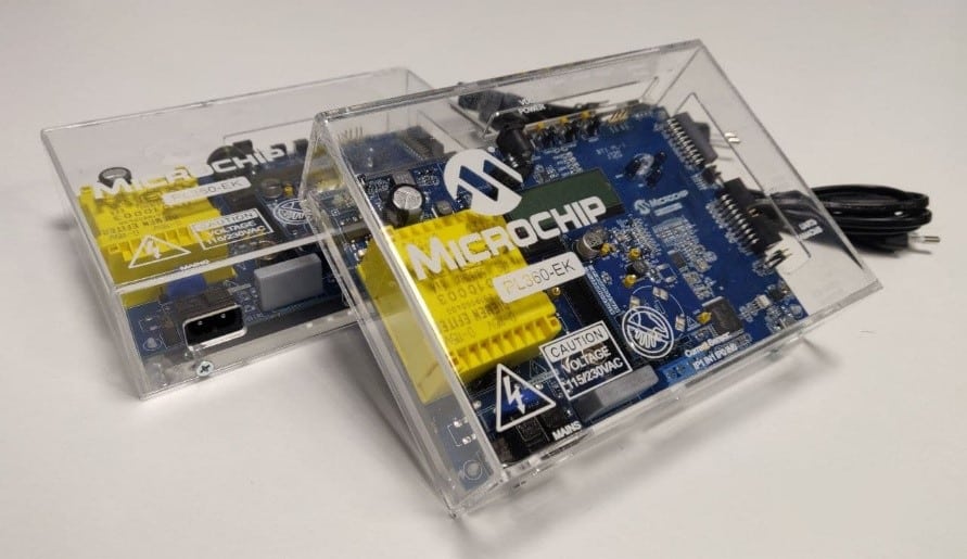
Description of the ATPL360-EK, evaluation kit and where to find it
The ATPL360-EK Development Kit is a Microchip product for those planning to use the PL360 device, a chip for PLC communications.
It is a generic board that serves to test the chip and verify that it meets the capabilities of what a hardware developer needs, but without having to invest time and money in manufacturing an initial prototype. This kit is designed to develop products that communicate with each other and therefore in the kit 2 plates are supplied together.
In addition, it is a product aimed at testing devices with the intention that the developer has to modify or add the minimum possible hardware, so the boards include more elements than PLCTool uses.
For the above reasons, development kits are usually a good alternative for testing hardware, but they are usually expensive solutions for the user.
You can buy the plates on the manufacturer’s own website:
Other options are these other distributors:
- https://www.mouser.es/ProductDetail/Microchip-Technology-Atmel/ATPL360-EK?qs=sGAEpiMZZMv0NwlthflBi7toauvDiO2Fi8gkcpQGbto%3D
- https://www.digikey.es/es/products/detail/microchip-technology/ATPL360-EK/8037696
Programming the ATPL360-EK evaluation kit
As discussed above, Microchip’s ATPL360-EK development kit must be programmed before use. If you have obtained your kit in the draw of the RootedCON 2022 talk you can skip this step, since your kit is already programmed.
To program the board it is necessary to compile the Candleblow project, which can be downloaded from the repository and install the IDE Microchip Studio 7.
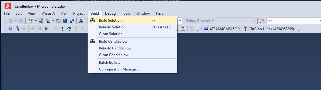
Once the source code is downloaded and Microchip Studio installed, the solution file “Candleblow.atsln” must be opened. Microchip Studio will be launched, where we can press F7 to compile or click on “Build” > “Build Solution” as seen in the image.
Once the solution is compiled, if there has been no problem, you can continue to write the code in the evaluation kit, for which a 20-pin JTAG programmer for ARM like this one will be necessary.
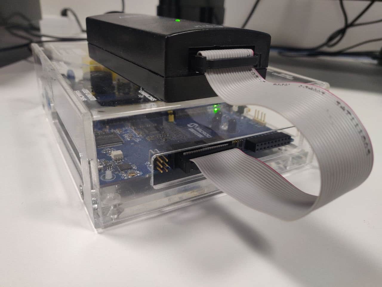
First, the programmer must be connected to the evaluation kit and PC and checked for successful detection in the Tools > Device Programming menu option. To do this, select the developer device from the drop-down list in Device, press the Apply button and then the Read button in Device Signature or Target Voltage.
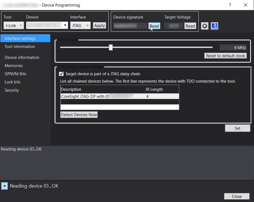
If both parameters are read correctly, the programmer has been successfully connected and the memory can be written by pressing F5 or the Start Debugging button.
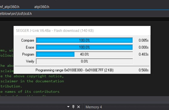
Once the evaluation kit is programmed, it is ready to be used with PLCTool.
Compiling and installing PLCTool
The tool has been developed with Qt and C/C++ and is a small tool with few dependencies, mainly:
- A C++ compiler (gcc 8.3.1 or later)
- The development files of Qt 5, version 5.9.1
To compile the tool, you simply download the source files from the repository and run the following commands:
% cd PLCTool
% qmake PLCTool.pro
% make
Having compiled the tool, you can run with:
% ./PLCTool
You can also use the Qt IDE, QtCreator, to open the project with the PLCTool.pro file, compile it and run the tool.
PLCTool usage
Usage with the ATPL360-EK evaluation kit
As indicated in the introduction and in the programming of the development kit section, to connect the host to a PLC network, an adapter such as the ATPL360-EK development kit and the firmware Candleblow, developed for this purpose, are needed.
When connecting the development kit to a USB port on the host, a /dev/ttyACMX serial device will appear on the Linux machine, where X will be a number representing the order of the device according to how many have been previously connected. If no more devices of the same type are connected, it will be /dev/ttyACM0.
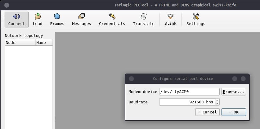
To connect PLCTool to the device simply use the Connect button in the upper left corner and a dialog will open to indicate the device and the transmission rate, in baud or bits per second, for serial port communication. In the default configuration, the firmware uses a transmission rate of 921,600 baud.
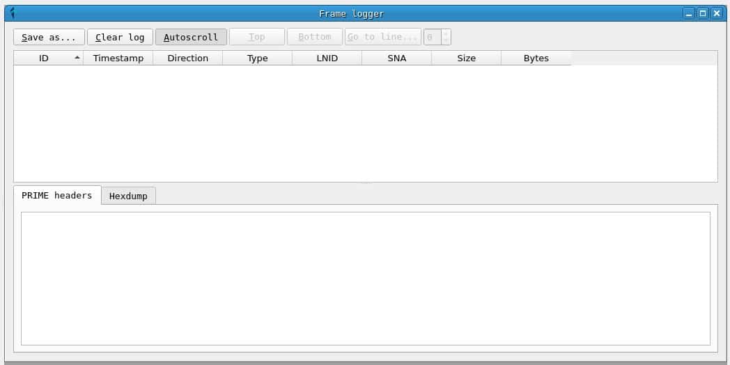
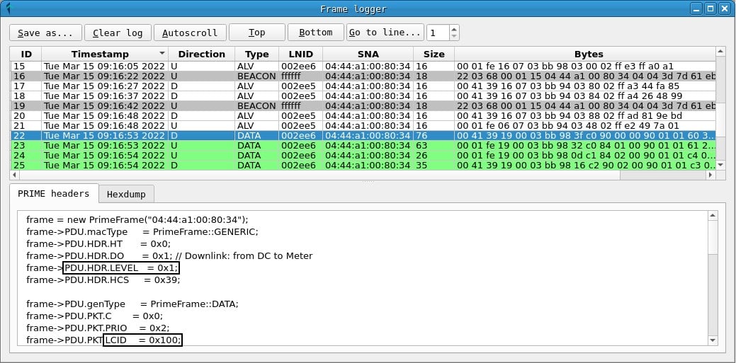
If the connection with the serial device has been correct, a window called Frame logger will appear, where the PRIME frames will be recorded as they are captured. From this point, you can leave the tool capturing. In many cases with a 24h capture, if the PRIME installation is not particularly secure, DLMS messages and passwords will be found in the credentials tab.
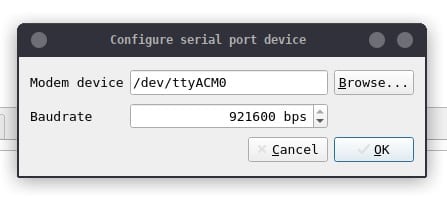
Clicking the Connect button again disconnects the adapter. You can also modify the connection parameters (the location of the device and the transmission speed) by clicking on the Settings button.
Network topology
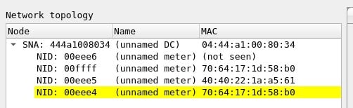
On the side of the main window, you can see the topology of the network from which packets have been captured:
- The network address, the SNA, corresponds to the EUI-48 address (MAC address) of the concentrator.
- Node identifiers, the NIDs, are assigned by the hub when a meter is registered on the network and can vary between registrations.
- Along with the NETWORK ANS and the NID of each meter, the EUI-48 address of the node appears if it has been captured, so that the meters can be uniquely identified.
In addition, of the meters highlighted in yellow, clear text passwords have been captured, which can be consulted in the credentials window or in the meter information window.
Meter information
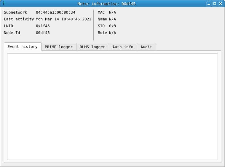
Clicking on the NID of a meter opens the Meter Information window, which contains information about the node and different tabs that contain the prime frames, as well as the DLMS messages and passwords captured.
The information displayed is the information captured for each meter, which means that counters with partial information can be found in the topology and in the information window. In many cases, the MAC address of the counter is only observed when a REG registration message is read, so for counters that are already registered the message will not be displayed until they are re-registered.
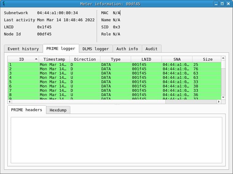
Frames and messages
The word frame is used to refer to PRIME PDUs, and the word message is used to refer to DLMS PDUs.
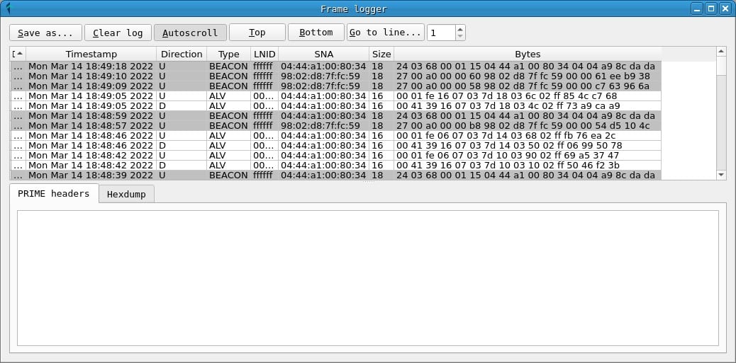
In the Frames window you can get a chronological list of captured prime frames. For each one, the following fields are displayed:
- A frame ID, assigned by PLCTool when capturing it.
- The timestamp.
- The frame address: D or downlink indicates the address of the hub to the counter and U or upstream indicates that the message is sent from the counter to the hub.
- The PRIME frame type.
- The LNID (local node identifier) of the meter sending or receiving the frame.
- The SNA (subnet address) of the network on which the frame has been sent.
- The total size of the frame.
- A hexadecimal representation of the frame bytes.
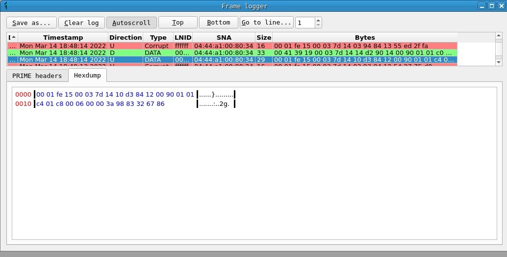
In addition, in the PRIME headers tab, the values of the PRIME header fields can be obtained, while the Hexdump tab displays a hexadecimal representation of the frame.
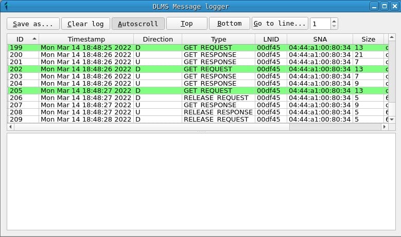
In the Messages window you can get a list of captured DLMS messages. The fields are as follows:
- An identifier of the order of receipt of the message.
- A timestamp.
- The message address: D or downlink and U or uplink.
- The type of DLMS message.
- The LNID of the counter that receives or sends the message.
- The SNA address of the network.
- The size of the message in bytes.
- A hexadecimal representation of the message bytes.
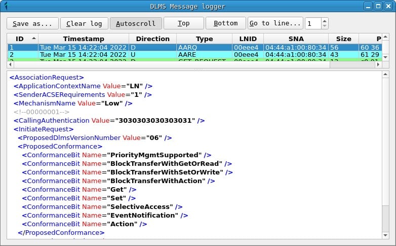
In the lower tab of the window an XML representation of the message fields is displayed to make it easier to read.
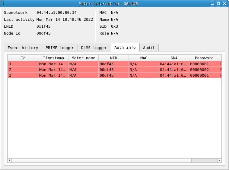
Credential Logger
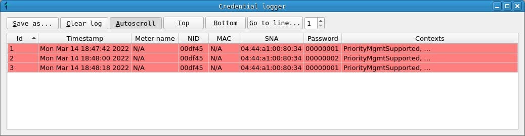
In the credentials window you can consult the passwords that have been obtained during the capture, indicating the NID of the counter and the SNA of the network in which it was used.
DLMS translator
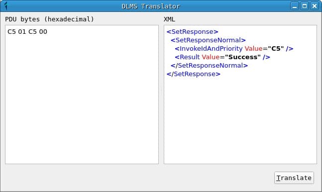
The translator window allows you to translate a DLMS message from hexadecimal format to XML format to display the fields. This tool uses the gurux library to do the translation and is very useful to study the packets that are received from a network, since the DLMS protocol standard is partially private and, in many cases, this service must be used to study the content of the messages.
Attack execution
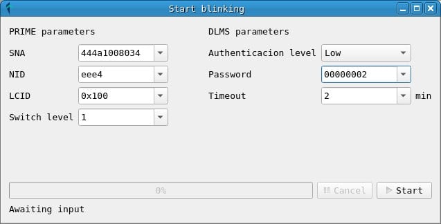
Next to the translator button, there are the triggers for the attacks. In the current version, a test attack has been implemented for the connection and disconnection of a counter: BlinkAttack.
For the execution of this attack it is only necessary to know the SNA of the network, the NID of the counter, the LCID, the switch level and the password.
The parameters of the attack can be obtained from captured messages:
- The SNA and NID are obtained from any PRIME frame or from the network topology.
- The LCID is a connection identifier within a node and usually has the value 0x100 for frames with DLMS messages. In either case, you can check the LCID between a meter and a concentrator by checking a frame with data (DLMS) sent between them. Other frame types, such as BEACON and REG may have different LCID values, but they are not useful for frames with DLMS messages.
- Switch level refers to the number of switch nodes (repeaters) between the meter and the concentrator. Usually this value is 0, since there are no switch nodes, although it can be checked by reading the frames received for a meter.
- Finally, the password may have been captured during an exchange of DLMS messages between the concentrator and the meter. From what has been proven during the investigation, in many cases, the password used to request actions on the meters, such as connection and disconnection, is 00000002.
You can also specify a timeout in minutes, in case the execution of the attack takes longer than this time.
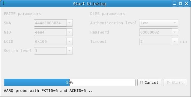
Clicking on the Start button initiates the attack, which consists of injecting DLMS messages that request disconnection and connection of the counter alternately. This initiates the sequence of connection and disconnection of a meter demonstrated during the talk.
Conclusions
With this guide a researcher will be able to start their own research of the smart meter infrastructure and audit the existing security.
The PLCTool project has listening and analysis functionalities, along with an attack infrastructure on which new and more features can be implemented. The attack implemented in the current version is designed to demonstrate the potential harm that insecure implementations of PRIME networks can cause and should be executed with caution in controlled environments.
For those interested, they can continue reading the previous posts of the research and collaborate in the development of the project.
Discover our work and cybersecurity services.
This article is part of a series of articles about Smart Meters
- Smart Meters – The Spanish Scenario and the Telemanagement System
- Smart Meters – Threats and Attacks to PRIME Meters
- Smart Meters – A proof of concept: hacking a smart meter
- Smart Meters – Assessing Concentrator Risk
- Security in PRIME networks – Current status
- PLCTool, the Swiss army knife of smart meters
- PLCTool plugin support