
Cybersecurity in LoRa and LoRaWAN: Context and Background
Since the beginning of the 21st century, the concept of Internet of Things (IoT) has gradually evolved from the initial vague ideas related to the interconnection of everyday objects to a better-defined system of integrated technologies, practices and infrastructures.
These objects can have ubiquitous connectivity thanks to Low Power Wide Area Networks (LPWAN), an umbrella term that encompasses various wireless and narrowband communication technologies, such as LoRaWAN, SigFox or ZigBee, which allow devices to interconnect with relatively low power consumption. However, from the point of view of cybersecurity, as these networks become more widespread, the attack surface of systems is significantly increasing. As such, a comprehensive study of these networks turns out to be essential.
Given the growing popularity of these networks, the next series of articles will be focused on the security of LoRaWAN networks, covering from the physical layer to higher level deployments.
LoRa and LoRaWAN
LoRaWAN is a low-power and long-range wireless communication technology, based on networks deployed in star-on-star topology, allowing IoT devices to connect with LoRaWAN gateways, which are in turn connected via IP networks to network and application servers.
LoRaWAN devices enable wireless communication with gateways typically by using the LoRa standard and operating in ISM bands. At this point it is important to explain the difference between LoRa and LoRaWAN: while LoRa is a physical layer technology that defines how low-powered devices communicate wirelessly with each other by using a proprietary narrowband modulation technique called CCS (Chirp Spread Spectrum), LoRaWAN is a medium access control (MAC) technology for star-topology networks, providing authentication, encryption and dynamic bandwidth adaptation, among other services.
The LoRaWAN specification, unlike LoRA, was released by the LoRa Alliance and is available in two major versions, 1.0 and 1.1, which basically differ in key management.
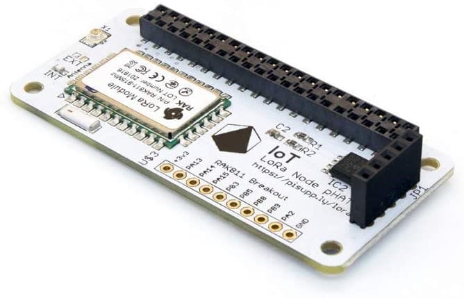
Although the LoRa protocol is a closed proprietary specification restricted to LoRa chip manufacturers, its structure and details were revealed after reverse engineering operations conducted by Matthew Knight and Balint Seeber. Their research also resulted in the development of a GNU Radio module (gr-lora), the source code of which can be freely downloaded from GitHub.
Unveiling LoRa
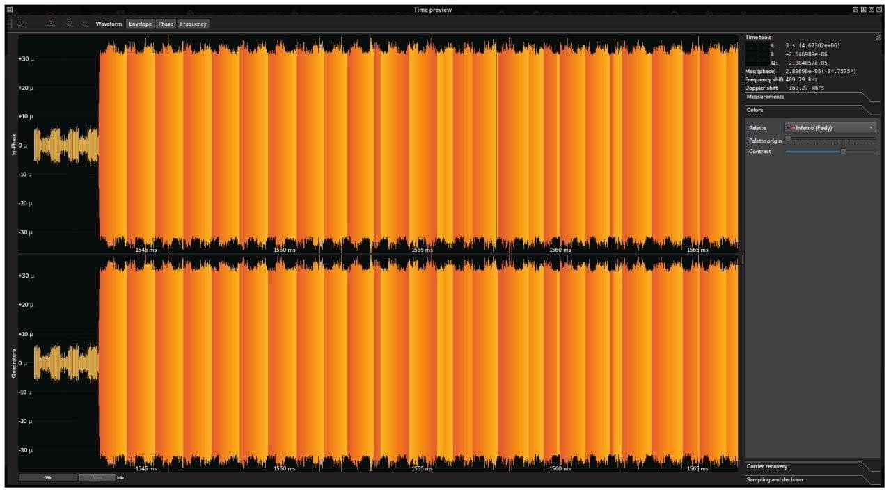
LoRa is a physical layer protocol used in wireless communications, designed and owned by Semtech to operate in ISM bands around 900 MHz, though the exact frequency depends on the region. For instance, the most commonly used operating frequency in the European Union is around 868 MHz. ISM bands support a number of communication technologies that need to comply with legally binding standards regarding acceptance, power and duty cycle (which is between 0.1% and 1% for these bands). Due to this, data are sent by LoRa in the form of bursts of limited duration and frequency, allowing for a few seconds to elapse between each packet of frames.
In order to improve resilience to interference, LoRa employs a spread spectrum modulation, called Chirp Spread Spectrum (CSS), a technique that encodes digital information as chirps or changes in frequency ramps within channel limits:
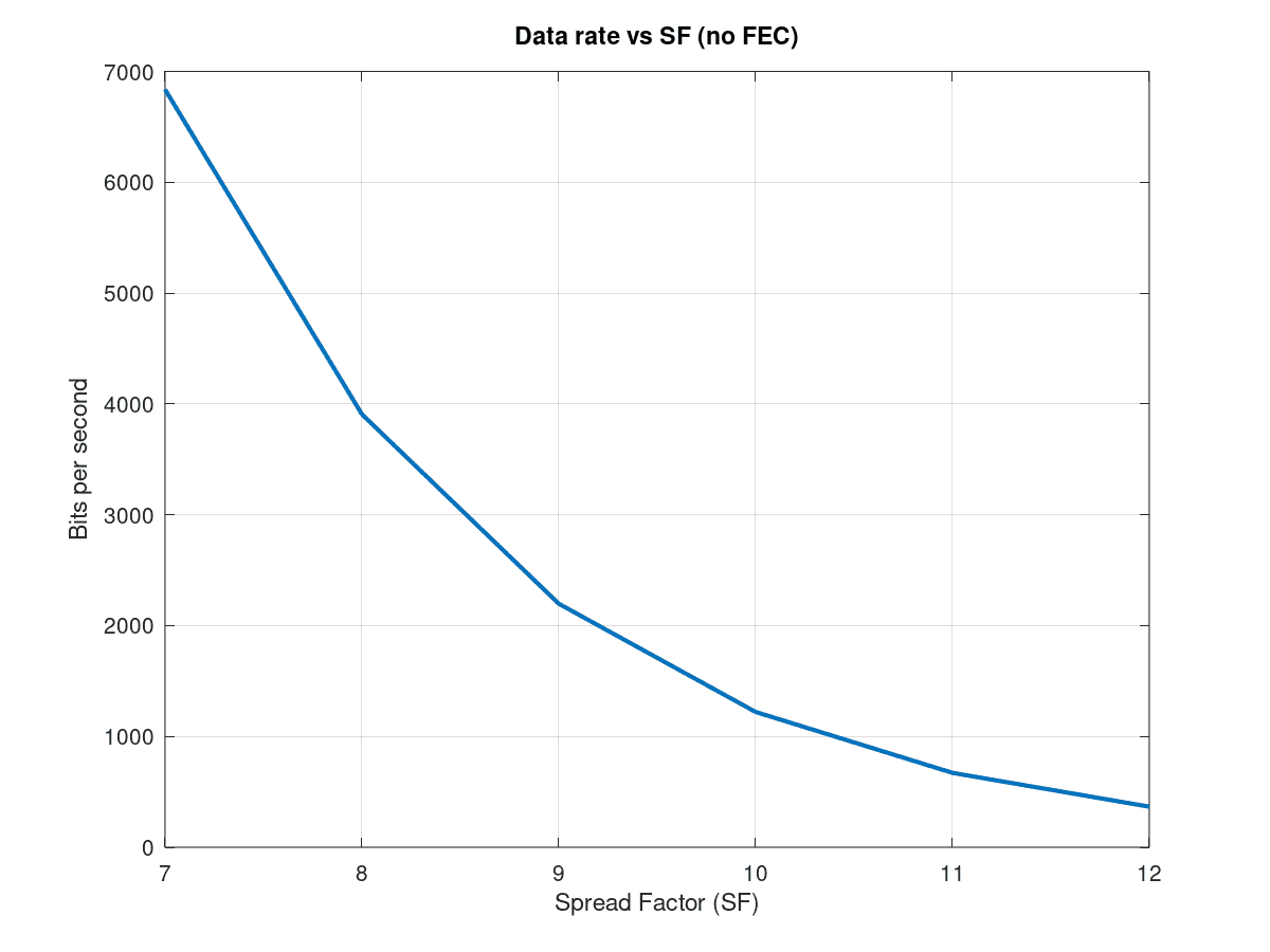
In the European Union (ITU Region 1), the 868 MHz band is divided into 10 LoRa channels, with bandwidths ranging from 125 to 250 kHz for uplink communications (node to gateway) and 125 kHz for downlink channels (gateway to node). Given the fixed bandwidth of these channels, the transmission bit rate is controlled by adjusting two parameters: the spreading factor (SF) and the chirp rate (CR), which are, respectively, synonyms of bits per symbol (accepting values between 7 and 12) and symbol rate. The above parameters are not independent, as the symbol rate is calculated from the bits per symbol value, and is given by channel bandwidth divided by 2SF. Consequently, increasing the SF in one unit (one bit) doubles the amount of symbols to be coded, and at the same time, halves the amount of chirps to be sent.
In practice, as the amount of bits per unit of time is calculated as the product of CR by SF, and given that a linear increase of SF results in an exponential decrease of CR, it turns out that the higher the SF is, the lower the data rate. This allows the data rate to be adjusted depending on factors such as channel contention, noise, etc.
In order to increase the transmission resilience, information is encoded before it is sent over the air. The steps are the following:
- Symbols are indexed in Gray code, in such a way that two adjacent symbols only differ in one bit.
- Randomness is then induced into the information bits by applying a whitening sequence consisting on an XOR operation. The whitening sequence does not correspond to any of those documented by Semtech, though it was experimentally derived by Knight and Seeber (2016).
- Bits are scrambled by using a diagonal interleaver. Although this is not described in Semtech patents, the interleaving algorithm was also experimentally deciphered by Knight and Seeber (2016).
- Information becomes redundant by the use of Hamming codes with four different rates (4/5, 4/6, 4/7 and 4/8) and non-standard bit orders.
As a consequence of the above encoding steps, especially due to parity bits added by Hamming codes, data rate is lowered while protection against noise and interferences is increased.
Once the receiver is synchronized with a burst preamble and has decoded the information, a LoRa PHY frame with the following structure is obtained:
| Preamble | Header (4/8) | Payload (4/N) | CRC (optional) |
Where the header is encoded at a fixed code rate of 4/8 (the highest redundancy allowed) and information about the payload size, payload code rate and the presence of a cyclic redundancy check (CRC) is provided. This payload contains LoRaWAN frames (MAC frames).
Unveiling LoRaWAN
As explained above, LoRa PHY defines how packets are transmitted in the physical layer, while LoRaWAN specifies how those packets are used to create networks. Besides, unlike LoRa PHY, the LoRaWAN specification is free and allows for open implementations.
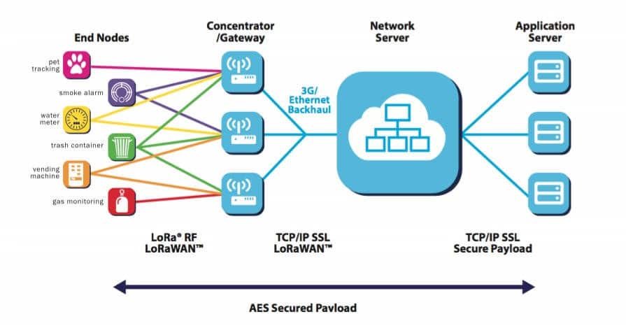
LoRaWAN networks are deployed in a star topology, where one or more end nodes communicate with one or more concentrators / gateways using LoRa PHY. Information received by LoRa gateways is then sent to application servers using an IP-based backhaul network, allowing these servers to respond to the received frames. LoRaWan also provides authentication, confidentiality and integrity services using AES-128 encryption.
The network server is positioned between the gateways and the application servers, and is responsible for managing the network access, discarding duplicated packets, adapting data rates, identifying the most suitable gateway to send back an acknowledgement message to application servers, etc.
Under this architecture, the join server is responsible for network server authentication and for end devices to be added to the network, while the network server manages other MAC services.
Unique identifiers are assigned to each element in the network, so as to be clearly distinguished from others. These identifiers are the following:
- DevEUI: 64-bit identifier, managed by the manufacturer, assigned to each end device.
- AppEUI: 64-bit identifier, managed by the join server operator, assigned to each application server located at the other end of the network.
- DevAddr: 32-bit identifier, managed by the network server, assigned to each end device after completing the network activation procedure. Similarly to IP addresses, the network identifier (NetID), assigned by the LoRa Alliance, contains up to 24 of the most significant bits of the DevAddr. NetID allows roaming devices to use coverage of other networks to access the home network.
Although LoRa communication is exclusively performed between the end nodes and the gateways, LoRaWAN MAC layer services are implemented by the network server. Gateways in LoRaWAN networks simply route the LoRa frames received from ISM bands and the backhaul network. As a result, interacting with the LoRa MAC layer implies interacting with the network server.
From the cybersecurity perspective, communications are protected with AES-128 for message encryption and signing, ensuring confidentiality and integrity to a certain extent. In fact, communication between nodes and network and application servers motivates the use of two AES-128 keys: one is used to protect metadata in the MAC layer (network session key or NwkSKey) while the second is used to encrypt the application payloads (application session key or AppSKey).
The activation procedure is used to register end devices as permitted to join the network and generate the corresponding keys. LoRaWAN offers two activation methods:
- OTAA (Over-The-Air Activation): This is the simplest and most suitable method. The end node sends a “Join Request” as a MAC packet containing the device DevEUI, the application server AppEUI to communicate with and a pseudo-random value called DevNonce. This request is also signed with a message integrity code (MIC) using a 128-bit key known as AppKey, which is pre-shared between the nodes, the network and the application servers. If MIC is validated using the AppKey, then the end node is authenticated.
When the request is accepted, the network sends back a “Join Accept” message that is also encrypted using the AppKey and includes the AppNonce and NetID parameters. Both ends generate ephemeral AppSKey / NewSKey keys, based on the information exchanged, which can be used for the duration of the session and until the next activation.
- ABP (Activation By Personalization): By using this mode, nodes have the DevAddr, NwkSKey and AppSkey set up in advance. As this information already exists, nodes can directly communicate with the network without sending Join messages.
As a general rule, OTAA is usually recommended, as the activation procedure generates two ephemeral session keys, AppSkey and NwkSkey, which are different for each session. In the case of ABP, the generation and lifetime of session keys is left at user discretion.
An important aspect to take into account when using the OTAA method in LoRaWAN v1.0 is that it is secured by using a key derivation algorithm given by:
NwkSKey = AES128(AppKey, 0x01|AppNonce|NetID|DevNonce|pad16)
AppSKey = AES128(AppKey, 0x02|AppNonce|NetID|DevNonce|pad16)
As AppSKey and NwkSKey are generated by using the same key material, it could be argued that the network server could use the exchanged tokens to derive the AppSKey. Besides, since the network server routes all the packets in the network, it could decrypt all the packets activated following the OTAA method. Accordingly, data security of applications in LoRaWAN v1.0 depends heavily on the reliability of the network infrastructure. For private deployments, where the network and the application servers share the same ownership, the only problem is that the same key is used for two different elements in the system. However, when the application server has a different ownership than the network service provider, one must implicitly rely on the goodwill of the second to not intercept private communications. This is, for instance, the case of The Things Network.
The above issue was fixed in LoRaWAN v1.1 specification, which adds a second authentication token (NwkKey), used solely to derive the network session key. However, due to the low expansion of LoRaWAN v1.1 and the vast number of devices only supporting LoRaWAN v1.0, there are two possible scenarios to downgrade to version 1.0:
- End device v1.1, network server v1.0: the end device ignores the existing AppKey and uses the NwkKey instead to derive both the AppSKey and the NwkSKey.
- End device v1.0, network server v1.1: although this case is not mentioned in the specification, when allowed, the network would have to use the AppKey to encrypt the application payloads and metadata in the MAC layer, which will bring us to the previous case.
In any case, validation of elements v1.0 within the network will face the same reliability concerns as described above. The next article will explore the consequences of backward compatibility and its impact on reliability of deployments.
Discover our work and cybersecurity services at www.tarlogic.com
This article is part of a series of articles about LoRaWAN
- Cybersecurity in LoRa and LoRaWAN: Context and Background
- LoRaWAN 1.0, vulnerabilities and backward compatibility in version 1.1